
PHONE:
0512-58581137 +86-13151198265
E-MAIL:
SKYPE:
zhujingke@hotmail.com
- All
- Product Name
- Product Keyword
- Product Model
- Product Summary
- Product Description
- Multi Field Search

Views: 0 Author: Site Editor Publish Time: 2026-09-23 Origin: Site


Installing a solar structure is a sequence with fixed order and fixed numbers, not a carpentry job carried out on the roof.
The order is consistent across system families: set out the array, install the attachment or foundation, build the rail or substructure, establish the bonding path, then clamp the modules. Roof-mount systems attach bases first and lay rails afterwards; ground-mount systems build foundations first and rails last; ballasted flat-roof systems start from a rated ballast plan rather than from a fixing plan.
The numbers come from two different manufacturers. The module maker sets the clamping zone and clamp torque; the racking maker sets the fastener torque for each part number. Tightening to a remembered value instead of the current manual is the most common avoidable defect on a solar structure installation.
Installation begins with four confirmations, not with a drill: the roof or soil can carry the design loads, the array layout fits the real structural members, the attachment and flashing method is acceptable to the roof system owner, and the fall-protection and electrical plans are in place.
This is not optional good practice. Racking manufacturers place the responsibility for confirming that the roof, rafters and connections can support all code-level loads on the party designing the installation, and require snow load, wind speed, exposure and topographic factors to be confirmed with the building official or a licensed engineer. If the array is designed from the module count alone, nothing downstream can repair the assumption.
Structural capacity. Verify the roof deck, rafters or purlins, and confirm the allowable dead load and any existing ballast or equipment already on the roof.
Design loads with the code edition. Record basic wind speed, exposure or terrain category, ground snow load and seismic parameters before selecting any component.
Member positions, not just spacing. Locate actual rafters or purlins so that every attachment lands on structure rather than on sheathing.
Clamping zone and rail span. Take the permitted zone, clamp length, frame overlap and clamp torque from the module manual, and the maximum rail span from the racking manual.
Waterproofing method. Agree the flashing detail with the roofing system owner before drilling; for flat roofs, confirm whether ballast is permitted at all.
Fall protection plan. In the U.S., construction fall protection is triggered at 6 feet (1.8 m) for roofing work, and personal fall arrest anchorages must withstand 5,000 pounds per worker.
Permits and inspection points. Confirm which stages an inspector must see, especially below-grade foundations and pre-cover bonding.
The OSHA fall protection requirements at 29 CFR 1926.501 are worth reading before the layout is fixed, because they shape how the array can be built as much as they shape the safety plan.
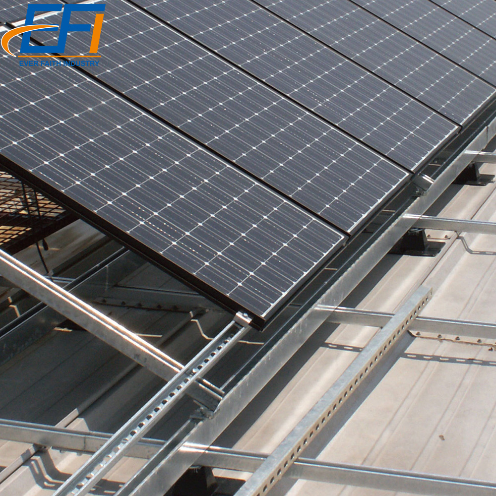
A pitched-roof solar structure is installed in a fixed order: attach the bases, place and join the rails, secure the bonding lug, then clamp the modules. Working in that order keeps every fixing reachable and every torque value verifiable.
Set out the array. Transfer rows from the general arrangement drawing, keep rows parallel and square with the roof edge, and mark every attachment over a structural member rather than over sheathing.
Install the bases. Fix L-feet, hanger bolts or standing-seam clamps to the structure, then torque to the value in the current manual for that part number. Flash or clamp every attachment — a gasketed fastener left exposed on a steep-slope roof is generally accepted as unlikely to stay watertight long term.
Place and splice the rails. Rails normally run perpendicular to the module long side. Insert splices to the depth stated in the manual and keep splices out of the mid-span of the modules. Where a continuous row becomes long, expansion joints are required — one major system specifies them once a row exceeds about 100 feet (30 m) of rail.
Secure the bonding or grounding lug. Fit the lug to the rail line and land the conductor; one lug per continuous subarray is the common pattern. This step comes before the modules because the connection point is easier to reach while the rail is still exposed.
Clamp the modules. Position mid clamps and end clamps inside the module maker's permitted clamping zone, check the required overlap over the frame and the minimum clamp length, then torque to the module manual value. Read the zone table rather than the torque table first: the zone decides the pressure rating.
Inspect and record. Photograph each attachment and flashing, mark torqued fasteners, record rail splice positions and clearances, and check that no module frame is short of clamps.
The step order above matches the published sequence of a widely used roof-mount system, whose manual runs from attaching bases to placing rails, securing the lug and finally clamping modules. Following the same logic is more reliable than improvising, because each step creates the access that the next one needs.
Torque values change between product generations.
One roof-mount system's L-foot torque was raised from 204 to 250 in-lb between manual versions, and its clamp and grounding-lug values also changed. Using a number remembered from an older project, or copied from a different manufacturer's manual, is a real defect rather than a rounding error. Always work from the manual revision that matches the part number on site.
Ballasted flat-roof installation is a load problem before it is an assembly task: the array is laid out from a rated ballast plan, blocks are placed per bay and per zone, perimeter deflectors close the array, and the whole arrangement is checked against the roof's dead-load capacity.
A ballasted system's capacity is expressed as an allowable load in pounds per square foot, and it is bounded by roof pitch. One widely used flat-roof system is rated at 30 psf downward, 15 psf uplift and 5 psf lateral, is limited to roofs of about 7 degrees or less, and holds up to four full-size or eight half-size concrete blocks per bay. Its Class A fire classification applies only on pitches below 2:12. Those are the numbers that determine how many blocks go on the roof — not convenience.
Confirm the roof can take the array. Verify the deck and structure for the combined dead load of modules, rails, blocks and deflectors, and confirm that the membrane and insulation can take the point loads without being damaged.
Confirm that ballast is allowed. Roofing authorities have raised explicit objections to ballasted racks, including point loads exceeding insulation compressive strength and lateral movement abrading single-ply membranes. Settle the warranty position before mobilising.
Set out from the ballast plan. Mark rows, perimeter setbacks and separation from fixed objects and array edges. A stamped commercial project used a 12 inch seismic separation between arrays and larger setbacks at roof edges depending on parapet height.
Place bays and base rails. Start at the south perimeter and work back, keeping bay spacing per the design so that the blocks sit where they were calculated to sit.
Install ballast to the plan, per zone. Perimeter and corner positions usually need more ballast than the interior. A stamped 18.26 kW project required roughly 108 lb of ballast per module across 44 modules, using blocks that satisfy a concrete specification.
Close the perimeter. Fit wind deflectors and clamps, and torque their hardware to the manual value, so the perimeter of the array is not held down by the interior ballast alone.
Clamp the modules and protect the membrane. Leave the specified thermal gap between modules, keep blocks on protective pads where required, and record the installed block count against the design count bay by bay.
The IronRidge BX flat-roof system installation manual is a useful reference for the structure of a rated ballast design, because it states the allowable loads, pitch limits and fire classification conditions rather than only the assembly steps.
Ballasted arrays have moved at wind speeds below their design value.
Full-scale wind testing of rooftop arrays found that peak loads occur toward the roof centre rather than at the edges, the opposite of the pattern on a bare roof, and that ballasted arrays can slide or lift well below the nominal design wind speed. That finding is the reason perimeter ballast, deflectors and as-built block counts matter more than the average ballast weight on a drawing.
Ground-mount installation starts below grade: foundations are installed to the design embedment and torque, then the substructure, rails, bonding and modules follow, with row spacing set from the lowest winter sun angle so rows do not shade each other.
Set out foundations and row spacing. Row spacing is a geometric consequence of module height and array tilt at the worst sun angle of the year, commonly evaluated at the December solstice in the morning. North-to-south pier spacing in one major system is either 7.5 or 9 feet, and the layout drawing, not the tape measure, decides which.
Install the foundations. Drive ground screws at low rotation speed and log torque against depth until the design torque is reached; verify embedment against the design, and remember that screw length must also clear the frost line in cold climates — one system's minimum screw length is 1,300 mm, with longer screws where wind, snow or freeze-thaw demand them. Concrete piers follow the footing design instead.
Mount the piers or posts. Set posts to the design height and insert the pile into the pier or ground screw to the required depth — a common requirement is at least 22 inches of insertion — then torque the set screws by member type.
Build the substructure. Fit top caps and horizontal beams, keeping the structure square and level across the array before rails are loaded with modules.
Place the rails. Install rails to the drawing and torque the connectors; rails carry the modules, so they are the last structural element to be finalised before the array is filled.
Bond and clamp the modules. Fit grounding lugs — one per continuous subarray is typical — land the conductor, then clamp modules inside the module maker's zone.
The IronRidge ground-based mounting resources document this order as foundation first, then substructure, then rails, and provide the pier spacing, insertion depth and set-screw torque values that make the sequence checkable on site.
Torque values and clamp positions are not interchangeable between products. The module manufacturer sets the clamping zone, clamp length, frame overlap and clamp torque; the racking manufacturer sets the fastener torque for every part number; and both change between generations.
Item | Published value | Where the value comes from |
|---|---|---|
Module clamp zone, rails perpendicular to long side | 440–490 mm from the module edge in a representative frameless-edge case, giving 2400 Pa rear / 5400 Pa front rating | Module manufacturer installation manual |
Module clamp torque, M8 hardware | 16–20 N·m is typical; some manuals allow up to 26 N·m in an annex | Module manufacturer installation manual |
Clamp length and frame overlap | Minimum clamp length 50 mm, thickness 4 mm, frame overlap 8–12 mm in a representative manual | Module manufacturer installation manual |
Rail-to-roof attachment torque | Raised from 204 to 250 in-lb between manual revisions in one roof-mount system | Racking system installation manual, current revision |
Module clamp nut torque, 1/4-20 hardware | 84 in-lb in the earlier revision of the same roof-mount system | Racking system installation manual, current revision |
Ground-mount set screws | 75–120 ft-lb depending on pipe size and wall type in one ground-mount system | Racking system installation manual, current revision |
Ballast frame flange nuts | 30 ft-lb in a representative ballasted frame system | Racking system installation manual, current revision |
The Trina Solar Vertex series user manual shows how module-side values are published: the clamp position range, clamp length, clamp thickness, required frame overlap and M8 torque are given together, because they only mean anything as a set. A clamp of the right torque in the wrong position does not reproduce the tested load rating.
Racking-side values are published the same way, and they are revised. Because a part number can exist in more than one configuration, the only safe source is the manual revision that matches what was delivered. Where a project is large enough to justify it, torque values should be transcribed into the inspection checklist before work starts, so that the value recorded on site is the value the designer intended.
Three checks decide whether the installation is acceptable to everyone other than the installer: the roof must stay watertight, fire service access must be preserved, and the array must be bonded and, where the code requires it, capable of rapid shutdown.
Roofing authorities treat penetration and ballast differently from many installers. The National Roofing Contractors Association recommends flashed, flanged supports, describes exposed sealant or gasketed lag screws on steep-slope roofs as problematic and unlikely to provide long-term watertightness, and disputes ballasted racks where point loads can exceed the compressive strength of the insulation. The practical response is to keep the fasteners inside a flashed detail and to keep the drainage path clear, which is also what the NRCA guidance on photovoltaic installations describes.
Flashing, not sealant. Every penetration sits inside a flashed or clamped detail; sealant is a secondary defence, not the primary one.
Drainage and debris. Rails run with the fall of the roof where possible, and no part of the array blocks a drainage path or creates a debris trap.
Fire service access. Code-based practice keeps clear perimeter and internal pathways so firefighters can move on the roof; these widths should be confirmed with the authority having jurisdiction rather than assumed from a catalogue.
Membrane protection. Ballast, rails and feet sit on protective pads where the membrane requires it, and point loads are spread rather than concentrated.
Bonding continuity. Module frames, rails and the equipment grounding conductor are bonded by listed devices, and continuity is measured and recorded.
Rapid shutdown. Where required by the electrical code, the system must limit conductor voltage outside the array boundary within 30 seconds of shutdown, at no more than 30 volts outside the boundary and 80 volts inside it, unless a listed hazard control system is used instead.
Labelling. Shutdown devices, disconnects and the array boundary are labelled so that an emergency responder can identify them without a drawing.
Do not load a ballast design uniformly to save time.
Zone-specific ballast is what the calculation is based on. Adding blocks evenly across the array, or removing blocks from interior bays to save weight, invalidates the design even when the total mass on the roof is unchanged.
Before handover, verify the installation against the design on six points: attachment and clamp positions, torque records, bonding continuity, clearances, thermal expansion gaps and the as-built drawing.
Positions. Compare the installed clamp positions with the permitted clamping zone and the installed attachment positions with the structural layout.
Torque records. Every fastening group has a recorded value, taken from the current manual. Marking torqued fasteners with paint is a useful secondary check but is not a substitute for the record.
Bonding continuity. Measure and record continuity across the array, including the module frames, rail splices and the equipment grounding conductor termination.
Clearances and gaps. Confirm module-to-roof clearance, module-to-module thermal gaps and row spacing against the design.
Expansion and movement. Confirm that expansion joints exist where required, that rail splices are correctly seated, and that ballasted bays have the designed separation from fixed objects.
As-built documentation. Hand over drawings, coating and material certificates, ballast block counts by zone, torque records and inspection photographs, so the next inspection or repair does not start from assumptions.
Next step: match the mounting structure and its accessories to the load case before the installation sequence is fixed.
Review solar structure product configurations
Installing a solar structure reliably comes down to two habits. The first is following the published order of work for the system family in front of you, because the sequence exists to keep each component accessible and verifiable. The second is treating every number — clamping zone, clamp overlap, torque, ballast count, embedment depth — as belonging to a specific product and manual revision rather than to solar mounting in general.
The installations that fail inspection or fail in service are rarely the ones with exotic errors. They are the ones where the base was fixed before the rafters were found, where the clamp sat outside the zone the module was tested in, where the ballast plan was averaged, or where the torque value came from memory rather than from the manual.
Set out the array, install the attachment or foundation, build the rail or substructure, establish the bonding path, then clamp the modules, and finish with inspection records. Roof-mount systems attach bases before rails; ground-mount systems pour or drive foundations before substructure; ballasted systems place bays and ballast before modules.
Rail spacing is not a general rule — it is the maximum span permitted by the racking manufacturer for the rail section, load case and module clamping zone being used. The span table applies to the specific configuration, and exceeding it changes the load path rather than simply increasing deflection.
Clamp torque comes from the module manufacturer's installation manual and is typically specified for the thread size and hardware material used. For M8 hardware, 16 to 20 N·m is common for major module brands, with some manuals allowing a wider range in an annex. The racking manufacturer's manual governs the fasteners that join the structure to the building or the ground.
Yes, through ballasted flat-roof systems or clamped standing-seam metal roof attachments. Both avoid penetration but shift the risk: ballasted systems depend on ballast weight, roof load capacity and membrane protection, while clamped systems depend on the seam profile and the tested withdrawal capacity of the clamp.
They can be, if the ballast plan is followed zone by zone and the perimeter is treated separately. Full-scale testing has shown that rooftop arrays experience peak loads toward the roof centre and that ballasted arrays can slide or lift below their nominal design wind speed, so perimeter ballast and wind deflectors carry more of the margin than the average ballast figure suggests.

